

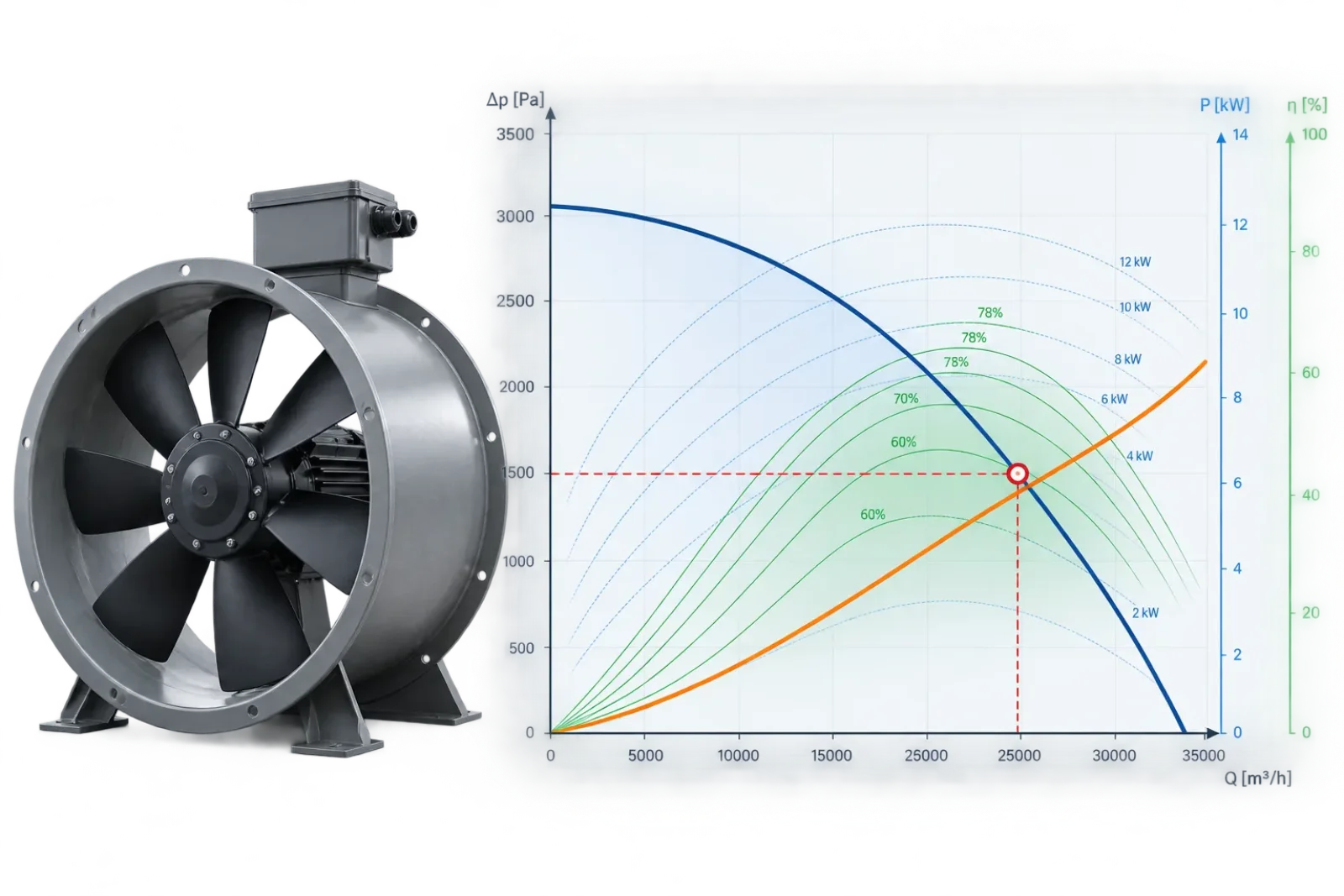
Fan selected for 10,000 m³/h. Commissioning reads 8,200. The fan may not be defective at all — it may simply be operating exactly where its curve and the actual system resistance dictate, at whatever static pressure the installed system is actually presenting. The airflow shortfall is a symptom; the cause is that the real system curve doesn't match the one the fan was selected against.
The mechanism, in one chart
A fan doesn't deliver a fixed airflow — it delivers whatever airflow puts it at the intersection of its own P-Q curve and the system's resistance curve (P ∝ Q²). Underestimate the system's resistance at the design stage, or add resistance the design calculation never accounted for, and that intersection point slides left along the fan curve: lower Q, higher P than the fan curve's design-point value.
Every cause below does exactly one of two things: it steepens the system curve (adds resistance the design calc missed), or it lowers the fan curve itself (the fan produces less than its rated curve at the same speed and density). Diagnosis is a matter of working out which.
Causes that steepen the system curve
- Underestimated ductwork resistance. Straight-run friction calculated correctly, but fitting losses (K-factors), transitions, and terminal device resistance under-accounted or omitted entirely. The most common single cause, and the easiest to audit against the original calculation.
- System Effect (AMCA 201). Non-uniform or swirling flow at the fan inlet or outlet imposes a pressure loss beyond what the ductwork calculation captures — it isn't a duct fitting loss, it's a fan-specific penalty for not giving the fan the uniform approach flow its rating was tested with. It's frequently the largest single unaccounted term in a system that's underperforming, precisely because it doesn't show up in a standard duct takeoff at all.
- Elbow or obstruction close-coupled to the inlet. The single most common System Effect trigger. An elbow within a few duct diameters of the fan inlet delivers a distorted, swirling velocity profile instead of uniform axial flow — the impeller sees an effectively smaller, non-uniform inlet and produces less than its rated curve at the same RPM.
- Duct leakage. Air escaping through unsealed joints between the fan and the terminal devices doesn't reduce the fan's own delivered airflow — the fan may be moving exactly its rated Q. What drops is airflow actually reaching the diffusers or process load, which is what commissioning measures. Distinguish this from a genuine fan-curve shortfall by checking flow at the fan discharge directly, not only at terminals.
- Progressive filter loading. A filter's rated pressure drop is a clean-condition, rated-velocity figure. Loaded resistance rises through its service life — a system balanced against a clean filter loses airflow as the filter loads, well before it hits its rated replacement ΔP.
Causes that lower the fan curve itself
- Incorrect running speed. Belt slip, a wrong sheave ratio on a belt-driven fan, or a VFD not actually at the commissioned frequency all mean the fan isn't running at the RPM its selection assumed. Fan laws are unforgiving here — airflow scales linearly with speed, so a 5% speed shortfall is a 5% airflow shortfall before anything else is even considered.
- Air density different from the rating condition. A fan curve is rated at a specific density. Altitude, temperature, or humidity different from that rating condition shifts the actual curve — see our density and altitude article for the mechanism.
- Outlet-side System Effect. A damper, a close-coupled elbow, or an obstruction at the fan discharge degrades output the same way an inlet disturbance does, just on the pressure side of the curve instead of the flow side.
Why the lab rating and the field result are never quite the same setup
AMCA 210 (and the equivalent ISO 5801) test setups use long, straight, uniform approach and discharge ductwork specifically to give the fan clean, undisturbed flow — the rated curve is a best-case aerodynamic condition by design. A real installation is a compromise between plant room space, structural constraints, and duct routing, and it very often can't replicate that. System Effect is the standard's own formal acknowledgment of that gap — a set of Category-based pressure adders precisely because "installed exactly like the test stand" is the exception, not the rule.
Inlet configuration: the highest-leverage single fix
A minimum straight, unobstructed run ahead of the fan inlet — AMCA 201 gives specific multiples of duct diameter depending on the disturbance type — restores the uniform approach velocity profile the fan's rating assumes. Where ducting space genuinely doesn't allow it, inlet vanes or turning vanes at the elbow reduce swirl intensity, though they don't eliminate the effect entirely.
Diagnostic order
- Confirm actual running speed against the design RPM (tachometer or VFD display, not the nameplate).
- Confirm density at the actual site/season condition against the rating condition.
- Inspect the inlet and outlet duct configuration for close-coupled elbows, dampers, or obstructions within a few diameters of the fan.
- Check filter condition and current pressure drop against its clean rating.
- Re-audit the original system resistance calculation for missing fittings, terminal devices, or System Effect allowances.
- Only after the above: consider duct leakage testing if delivered terminal airflow is short of measured fan discharge airflow.
Frequently asked questions
Why is my fan not producing the expected airflow?
The most common causes are higher-than-expected system resistance, incorrect fan speed, dirty filters, duct leakage, air density differences and System Effect caused by poor inlet or outlet conditions. The fan normally operates where its actual performance curve intersects the real system resistance curve.
Can high static pressure reduce fan airflow?
Yes. As system resistance increases, the operating point moves along the fan curve toward lower airflow and higher pressure. If the actual duct system requires more pressure than assumed during fan selection, the fan will usually deliver less airflow than expected.
How does a dirty filter affect fan airflow?
As a filter collects dust, its pressure drop increases. This adds resistance to the HVAC system and can move the fan operating point toward lower airflow. The effect can become significant even before the filter reaches its recommended final pressure drop.
Can an elbow near the fan inlet reduce airflow?
Yes. An elbow or other obstruction located too close to the fan inlet can create a distorted or swirling velocity profile. The fan then operates under different conditions from those used to establish its rated performance curve. This is known as System Effect and can reduce installed fan performance.
Does lower fan speed reduce airflow?
Yes. According to the fan affinity laws, airflow is approximately proportional to fan speed. For example, if a fan operates 5% below its intended RPM, its airflow will also be approximately 5% lower, assuming the same system and comparable operating conditions.
Can altitude or temperature reduce fan performance?
Yes. Temperature, altitude and humidity affect air density. A fan moves approximately the same volume of air at a given speed, but its pressure capability and power vary with density. This is particularly important for high-temperature applications and installations at significant altitude.
How can I find out whether the problem is the fan or the duct system?
Start by measuring the actual fan speed, airflow and pressure. Compare these values with the manufacturer's fan curve at the correct air density. Then check filter pressure drop, duct resistance and inlet/outlet conditions. If the fan operates correctly on its curve but airflow is too low, the problem is usually related to the system rather than the fan itself.
Why does my fan work correctly without ductwork but lose airflow after installation?
A fan tested without the complete duct system operates against much lower resistance. Once ducts, elbows, filters, dampers, grilles and other components are connected, the system resistance increases and the operating point changes. Poor inlet or outlet geometry can additionally introduce System Effect losses that are not apparent when the fan operates in free air.
Model it before you're on site
CloudAir's System Effect calculator quantifies the AMCA 201 pressure adder for a given inlet or outlet configuration directly. The Duct Network Configurator re-checks the full system resistance calculation against the actual installed geometry, and the Fan Operating Point calculator pulls speed, density and duty point together into a single check. Free, no sign-up.