

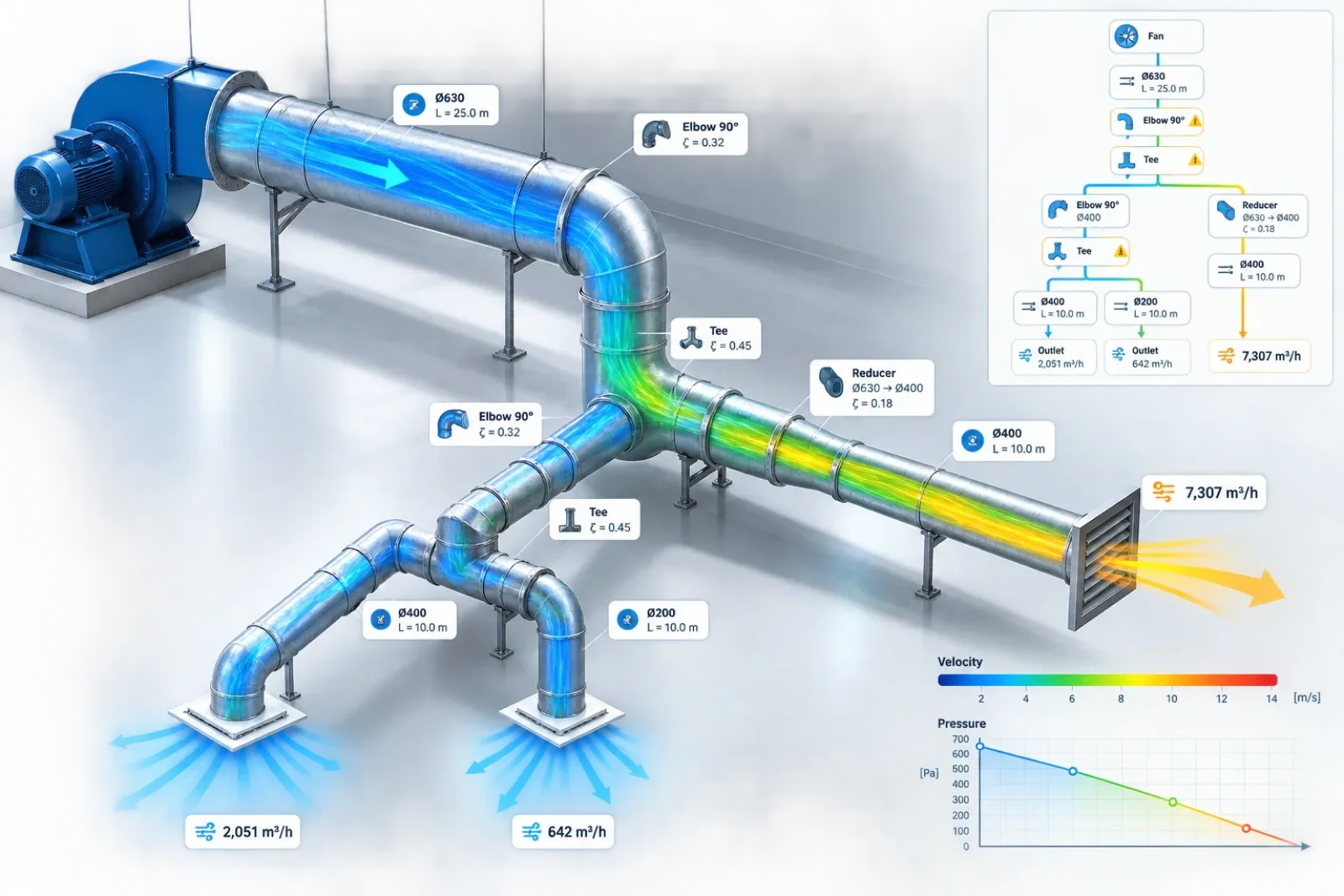
A fan doesn't know or care where the pressure it's fighting comes from — a metre of straight duct, a sharp elbow, a half-closed damper, a dirty filter, it all adds up to one number the fan has to overcome, all day, every day. Reduce that number and the fan needs less pressure, draws less power, and costs less to run — for the entire life of the system. Here's where that pressure actually comes from, and what genuinely reduces it.
Two completely different kinds of loss
Pressure loss in ductwork comes from exactly two sources, and they behave differently:
- Friction losses — air rubbing against the duct wall, all along its length. This is what the Darcy-Weisbach and Colebrook-White equations calculate: a steady, continuous pressure drop per metre of straight duct.
- Local (minor) losses — sudden, one-off losses at anything that disturbs the airflow: elbows, tees, dampers, filters, transitions. Despite the name "minor," these are very often the larger share of a real system's total loss.
Local losses are calculated differently from friction — not per metre, but as a multiple of the velocity pressure at that point in the duct:
ΔPlocal = K × (ρ · V² / 2)
K is a loss coefficient specific to that fitting — a gentle, large-radius elbow might have K ≈ 0.2; a sharp, mitred one can be K ≈ 1.0 or higher. A damper's K depends heavily on how far it's throttled. A filter's resistance is usually quoted directly by the manufacturer as a pressure drop at a rated face velocity, rather than as a K-factor at all.
What a real system actually adds up to
Take a straightforward branch: a fan feeding 15 m of straight duct, then a 90° elbow, an open damper, a clean filter, and an outlet grille — all at 8 m/s through a Ø315 mm duct. Here's what each stage actually costs, in pressure:
Notice the filter and the straight duct are the two largest single contributors here — not the fittings people tend to worry about most. This is exactly why a full system calculation, not just a straight-duct estimate, matters: the "minor" losses are frequently not minor at all.
Diameter and velocity: the two levers that matter most
Both friction losses and every local loss share the same dependency: they scale with velocity squared. Halve the velocity and every loss in the system — friction and local, together — drops to roughly a quarter. And since velocity for a given airflow is set entirely by duct cross-section area, that means duct diameter is the single biggest lever available for reducing system pressure loss.
The curves make the trade-off visible: pushing more velocity through a smaller duct buys compactness at a steeply rising pressure-loss cost. A slightly larger duct, moving the same air more slowly, can cut that loss dramatically.
Round or rectangular?
For the same cross-section area, round duct is aerodynamically more efficient than rectangular — it has proportionally less internal surface in contact with the airflow, which means less friction. Rectangular duct earns its place mainly on space grounds, fitting into shallow ceiling voids a round duct of equivalent area couldn't — not because it performs better.
The trade-off nobody can avoid: bigger duct costs more to buy, less to run
This is the real decision behind every duct sizing choice, and it never fully goes away:
- A bigger duct costs more upfront — more sheet metal, more insulation, more hangers, more ceiling void space — but delivers lower velocity, lower pressure loss, a smaller fan, less fan energy, and usually less noise, for as long as the building stands.
- A smaller duct costs less to install, but locks in higher velocity, higher pressure loss, a bigger fan, and higher running cost for the system's entire operating life.
The US Department of Energy's own guidance on duct system efficiency makes the same point directly: increasing duct diameter reduces velocity and friction loss, which reduces the fan energy the system consumes for as long as it operates — the capital cost difference is a one-time expense, but the running-cost difference compounds every year after.
How to actually optimise an installation
- Size for velocity, not just for the space available. Let a target velocity (or friction rate) drive the duct size, rather than fitting the largest duct that happens to squeeze into the ceiling void.
- Use gentle, large-radius fittings where the layout allows it. The difference in loss coefficient between a sharp mitred elbow and a smooth radius one is real and free to specify at design time.
- Don't leave dampers throttled as a permanent fix. A damper closed down to balance airflow is also permanently adding pressure loss — rebalancing the system design is often cheaper over time than living with a heavily throttled damper.
- Check the filter's contribution, not just the ductwork's. As the earlier breakdown shows, a filter can easily be the single largest loss in the whole branch — factor its rated (and its dirty, end-of-life) pressure drop into the system calculation, not just clean-duct friction.
- Calculate the whole path, not just the longest straight run. The branch with the most fittings, not the longest duct, is often the one that actually sets the fan's required pressure.
Frequently asked questions
What causes the most pressure loss in HVAC ductwork?
Pressure loss comes from both duct friction and local components such as elbows, tees, dampers, filters, transitions and grilles. In many real HVAC systems, filters and fittings can contribute as much or more pressure loss than the straight duct itself.
How can I reduce pressure drop in HVAC ducts?
The most effective method is usually to reduce air velocity by increasing the duct cross-sectional area. Pressure losses also decrease by using smoother and shorter duct runs, large-radius elbows, gradual transitions, properly sized filters and avoiding unnecessary throttling with dampers.
Does increasing duct size reduce pressure loss?
Yes. For the same airflow, a larger duct reduces air velocity and therefore friction and local pressure losses. Because many pressure losses are strongly related to velocity squared, even a moderate increase in duct size can significantly reduce the pressure required from the fan.
Why does pressure drop increase so quickly with air velocity?
Local pressure losses are proportional to dynamic pressure, which depends on the square of velocity: ΔP = K × ρV²/2. This means that doubling air velocity can produce approximately four times the local pressure loss, assuming other conditions remain unchanged. Friction losses also rise strongly with velocity.
Do elbows cause a large pressure drop in ductwork?
They can. A smooth, large-radius elbow creates much less resistance than a sharp or mitred elbow. The actual pressure loss depends on the elbow geometry, air velocity and its loss coefficient (K). Multiple poorly designed fittings can become a significant part of the total system resistance.
What is an acceptable pressure drop in HVAC ductwork?
There is no single acceptable pressure drop that applies to every HVAC system. The appropriate value depends on airflow, duct dimensions, system type, available fan pressure, noise requirements and energy targets. Rather than treating one pressure-drop value as universally correct, designers typically establish acceptable air velocities or friction rates for different parts of the system.
How does duct pressure loss affect fan energy consumption?
Higher system resistance requires the fan to generate more pressure. At the same airflow, this generally means greater fan power and higher electricity consumption. Reducing unnecessary duct resistance can therefore reduce both required fan pressure and long-term operating costs.
Calculate your own system
CloudAir's Duct Network Configurator builds out a full branching run — straight ducts, reducers, elbows, tees, dampers and louvers — and totals the real pressure loss down every path, the same Darcy-Weisbach and Colebrook-White physics used throughout this article. For a single duct, the Duct Sizing Calculator and Duct Pressure Drop Calculator give a faster answer. All free, no sign-up.