

Before selecting a fan, you need to know what the fan actually has to do. In almost every application that comes down to two numbers:
- Q: the required airflow,
- Ps or Pt: the required static or total pressure.
Together they define the required fan duty point. There is no single formula that works for every application: a fume cupboard is not calculated like a server room, a paint booth, a warehouse, a furnace or a machine-cooling system.
That idea is behind the duty point calculator we built into the CFB fan selection program. Instead of asking which ventilation formula to use, it asks "What are you ventilating?" and then "Which one exactly?", and the calculation method follows from the answer.

What is a fan duty point?
A duty point is the airflow and pressure the fan must deliver. For example, Q = 2,100 m³/h and Ps = 475 Pa means the selected fan must move about 2,100 m³/h while overcoming 475 Pa of system resistance.
The duty point has to be known before searching through fan models. Without it there is no way to tell whether a fan is suitable. How a selection program then uses it is explained in what is fan selection software.
Step 1: Decide what needs to be ventilated
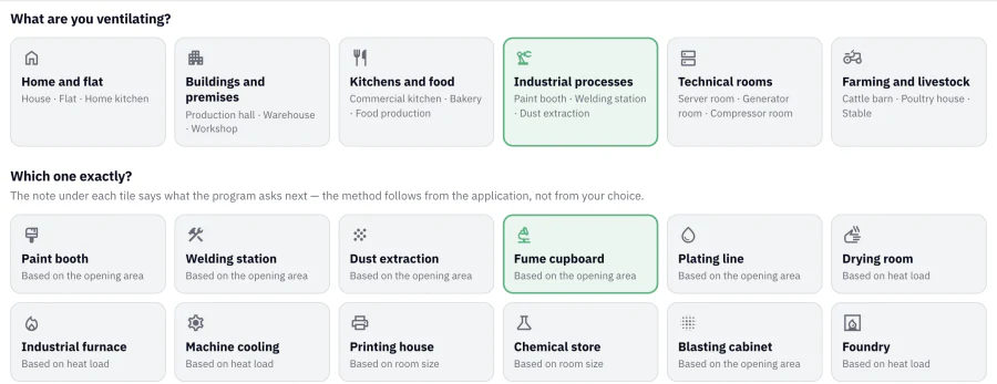
The first question is not "which fan do I need?" but "what is the ventilation application?" The CFB calculator groups applications into six areas:
- home and flat,
- buildings and premises,
- kitchens and food,
- industrial processes,
- technical rooms,
- farming and livestock.
Each area opens a list of specific applications. Under industrial processes, for example: paint booth, welding station, dust extraction, fume cupboard, plating line, drying room, industrial furnace, machine cooling, printing house, chemical store, blasting cabinet and foundry.
Different applications need different airflow methods
There is no universal equation such as room volume × one fixed factor. Depending on the application, airflow may follow from the opening area and a face or capture velocity, from room volume and air changes, from the heat load, from the number of people or rooms, from equipment dimensions or from pollutant generation. A good calculator picks the method from the application, so the user does not have to.
Method 1: Airflow from the opening area
Local exhaust is usually sized from the open area that has to be protected and the air velocity needed through it. Typical examples are fume cupboards, paint booths, blasting cabinets, extraction hoods and some welding applications.
Q = A × v → Q [m³/h] = A × v × 3,600Q airflow · A open area in m² · v face or capture velocity in m/s
Worked example: a fume cupboard
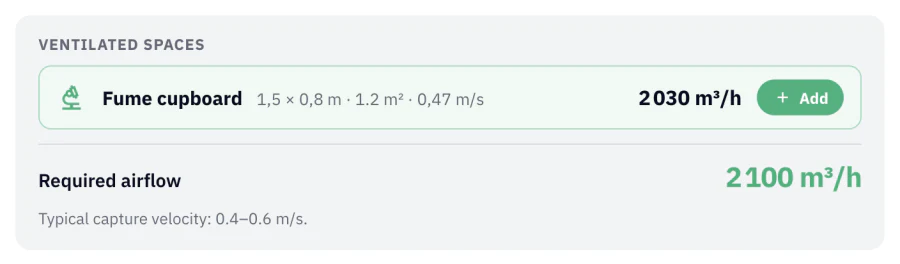
In the calculator, choose Industrial processes → Fume cupboard. The typical opening is filled in: 1.5 m wide and 0.8 m high.
A = 1.5 × 0.8 = 1.2 m²
Q = 1.2 × 0.47 × 3,600 ≈ 2,030 m³/h
With the normal ventilation intensity the program uses 0.47 m/s, inside the typical capture velocity range of 0.4–0.6 m/s that it displays. That gives about 2,030 m³/h, which it rounds up to a design requirement of 2,100 m³/h.
Normal vs intensive ventilation
The same opening can need very different airflow depending on the process. Switching the calculator to intensive raises the velocity to 0.6 m/s:
Q = 1.2 × 0.6 × 3,600 ≈ 2,590 m³/h → 2,600 m³/h
A change of 0.13 m/s in the required velocity adds about 500 m³/h, almost a quarter more air, and, as shown below, considerably more pressure.
Method 2: Airflow from room size
For many rooms, ventilation is estimated from air changes per hour (ACH):
Q = n × VQ airflow in m³/h · n air changes per hour · V room volume in m³
A 150 m³ room that needs 6 air changes per hour needs 6 × 150 = 900 m³/h. The calculator uses this method for production halls, warehouses, workshops, printing houses, chemical stores, houses and flats, among others. The right ACH depends strongly on the room's function, which is why the application is chosen first; typical values are collected in what is a good air change rate.
Method 3: Airflow from the heat load
Sometimes the main purpose of ventilation is to remove heat: machine cooling, server and electrical rooms, generator and compressor rooms, boiler rooms, furnaces, drying rooms and foundries. Airflow then follows from the heat that has to be carried away and the temperature rise that is acceptable:
Q = Φ / (ρ × cp × ΔT)Φ heat load in W · ρ air density ≈ 1.2 kg/m³ · cp ≈ 1,005 J/(kg·K) · ΔT permitted temperature rise in K
For a machine releasing 5 kW with a permitted rise of 5 K: 5,000 / (1.2 × 1,005 × 5) ≈ 0.83 m³/s, or about 2,985 m³/h. Halve the permitted rise and the airflow doubles.
Method 4: Process-specific airflow
Some applications cannot be described by a room-volume calculation at all:
- Paint booths: the open area and the air velocity through the booth dominate.
- Welding stations: fumes must be captured locally, not just diluted in the room.
- Dust extraction: capture conditions, transport velocity in the duct and the geometry of the extraction point decide.
- Fume cupboards: the face velocity and the sash opening are critical.
- Industrial furnaces and foundries: temperature, heat release, fumes, dust and process exhaust all play a part.
That is why the calculator asks for the exact application rather than presenting one generic HVAC formula. It also covers two simpler methods: by number of people (offices, classrooms, meeting rooms, gyms, dining rooms) and by number of rooms (home kitchens, bathrooms, toilets, laundry rooms).
Combining several ventilated spaces
A real system often serves more than one extraction point. In the calculator, each one is added as a separate ventilated space with the Add button, and the airflows are summed. For example:
| Ventilated space | Airflow |
|---|---|
| Fume cupboard 1 | 2,100 m³/h |
| Fume cupboard 2 | 1,800 m³/h |
| Process hood | 3,500 m³/h |
| Common system | 7,400 m³/h |
The total is the requirement for the shared system, subject to any simultaneity assumptions: if not all hoods run at once, the design airflow can be lower.
Airflow is only half of the duty point
Knowing that the system needs 2,100 m³/h is not enough to select a fan. The second question is: how much pressure must the fan generate to push that airflow through the system? That depends on the pressure losses of everything the air passes through:
- straight ducts, bends, elbows and transitions,
- branches and tees,
- dampers, filters, silencers, coils and heat exchangers,
- grilles, louvres, hoods and terminals,
- the process equipment itself.
How to estimate the required pressure
The required fan pressure is the sum of the relevant losses. The calculator's Help me estimate mode builds it from a few inputs: total duct length, number of elbows and branches, the duct design (large and quiet at 4 m/s, standard at 6 m/s or compact at 9 m/s), the duct shape and size, what the system does, and which components it contains. If you already know the pressure, I know the pressure lets you type it in.

For the fume cupboard, the program adds it up like this:
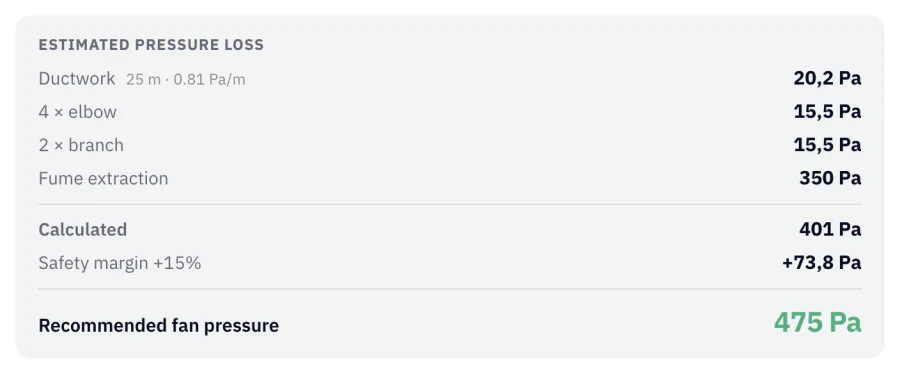
The required duty point for the fume cupboard is therefore Q = 2,100 m³/h at Ps = 475 Pa, and the fan can now be selected against a meaningful engineering requirement. For detailed duct losses, use the free duct pressure drop calculator.
Pressure drop grows with the square of airflow
In ventilation systems dominated by turbulent losses, pressure drop follows:
Δp = K × Q²
This matters a lot. If airflow rises by 20%, the pressure loss does not rise by 20%: 1.2² = 1.44, so it rises by about 44%. Oversizing the airflow therefore inflates the required pressure and the energy consumption at the same time.
The system curve
Once one point is known, the whole system curve follows:
Δp2 = Δp1 × (Q2 / Q1)²
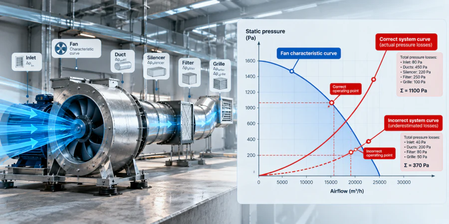
For the fume cupboard system (2,100 m³/h at 475 Pa), that gives about 242 Pa at 1,500 m³/h and about 969 Pa at 3,000 m³/h. The result is a parabola, and the fan's actual operating point will be where its curve crosses it.
An underestimated system curve is one of the most common reasons a fan disappoints on site. If the real losses are higher than assumed, the system curve is steeper, and the fan settles at a higher pressure and a lower airflow than planned:
More on this in why a fan does not deliver the expected airflow.
Static pressure or total pressure?
A duty point must state whether the pressure is static (Ps) or total (Pt):
Pt = Ps + Pv, Pv = ρ × v² / 2
In the ⌀400 mm duct of the example, at 4.6 m/s, the velocity pressure is about 1.2 × 4.6² / 2 ≈ 13 Pa. The fan curve and the system calculation must use the same definition: comparing a total-pressure fan curve with a static-pressure requirement, without accounting for velocity pressure, can lead to the wrong fan. The difference is explained in static vs total pressure.
Air density matters
Airflow is given as a volume, but fan performance also depends on air density, which changes with temperature, altitude, atmospheric pressure and humidity. That matters especially for furnaces, drying systems, hot-gas extraction and installations at altitude. That is why the calculator records the medium temperature as part of the duty point, next to airflow and pressure. See how temperature and altitude affect fan performance, or calculate it with the air density calculator.
Do not add arbitrary safety margins
A common habit is to calculate 10,000 m³/h and 500 Pa and then add 20% to everything. That produces an unnecessarily large fan, with a higher purchase price, a bigger motor, more noise, throttling losses and higher electricity consumption.
It is better to identify the real uncertainties and allow for them where they actually are:
- filter loading over time,
- uncertain duct routing,
- future extensions,
- damper resistance,
- system effect at the fan inlet and outlet,
- process variation.
The calculator follows that logic in a modest way: its 15% margin is applied only to the pressure and shown as its own line, so you can see that 74 of the 475 Pa are allowance, not calculated losses.
Required duty point vs actual operating point
The two are related, but not the same.
- The required duty point comes from the ventilation design, for example 2,100 m³/h at 475 Pa. It is what the application needs.
- The actual operating point exists only after a specific fan is chosen: it is where that fan's curve meets the real system curve.
A well-selected fan operates close to the required duty point, in an efficient and stable part of its curve. You can explore the intersection with the free fan operating point calculator.
From application to fan selection
That is far more reliable than starting from a fan model and trying to work out afterwards whether it fits. In the CFB program, the duty point panel ends with a Find suitable fans button, so the step from requirement to catalogue is one click.
Conclusion
Estimating the required airflow and pressure starts with understanding the application. Airflow may depend on the opening area and capture velocity, the room volume and air change rate, the heat load, the number of people or rooms, the equipment dimensions or pollutant generation. Pressure depends on the resistance of the complete system. Only when both are known should fan selection begin:
Application → airflow → system resistance → pressure → duty point → fan selection
A calculator that picks the method from the application, such as the duty point calculator in the CFB program, makes that first part quick and repeatable. If you want the same tool in your own selection software, see our fan selection software.
Frequently asked questions
How do I calculate the airflow for a fan?
It depends on the application. For local exhaust, multiply the open area by the required face or capture velocity (Q = A × v). For rooms, multiply the volume by the air changes per hour (Q = n × V). For heat removal, divide the heat load by ρ × cp × ΔT.
How do I estimate the pressure a fan needs?
Add up the pressure losses of everything the air passes through at the design airflow: ducts, elbows, branches, filters, silencers, dampers, grilles, hoods and the process equipment.
What airflow does a fume cupboard need?
Opening area × face velocity. A 1.5 × 0.8 m opening at 0.47 m/s needs about 2,030 m³/h, or 2,100 m³/h rounded up; at 0.6 m/s it needs about 2,600 m³/h. Always check local regulations and the cupboard manufacturer's data.
Why does a small increase in airflow need so much more pressure?
Because pressure loss grows with the square of airflow. 20% more air needs about 44% more pressure.
Should I add a safety margin to the duty point?
Only where there is a specific uncertainty, such as filter loading or uncertain duct routing. A blanket 20% on both airflow and pressure usually leads to an oversized, noisier and less efficient fan.