
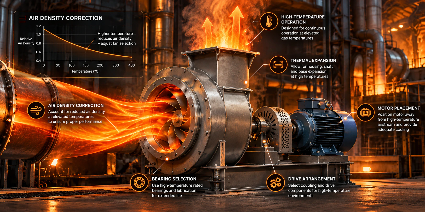
Standard ventilation fans are rated for ambient air, typically -20°C to +40°C. Drying ovens, process exhaust, kiln off-gas and smoke extraction all move air well outside that window — 150°C, 300°C, sometimes 600°C. Pick a fan the way you'd pick one for a clean room, and you get one or more of: bearing seizure within weeks, a motor that trips on overload the first hot day, a duct-mounted fan producing a third of the pressure the catalog curve promised, or a shaft that binds against the housing once everything reaches operating temperature.
None of this is exotic engineering. It's four things that change with temperature — air density, bearing life, material clearances and drive configuration — handled in the right order. This guide works through them with real numbers, then runs a complete worked example at 250°C.
1. Start with the actual gas temperature, not the process temperature
The number that matters is the air/gas temperature at the fan inlet, not the temperature quoted for the process. A dryer running at 180°C can deliver exhaust at 140°C by the time it reaches the fan, after duct losses and dilution air — or it can spike 40°C above nominal during a upset condition, which is exactly the number the fan has to survive, not just the average.
As a rough map of where different temperature bands typically land:
| Inlet temperature | Typical application | Common duty |
|---|---|---|
| 60–100°C | Drying systems, paint booths | Continuous |
| 100–200°C | Industrial ovens, kiln exhaust | Continuous |
| 200–300°C | Process gas exhaust, flue gas | Continuous |
| 300–400°C | Smoke extraction (general) | Emergency, timed |
| 400–600°C+ | Emergency smoke exhaust, tunnel ventilation | Emergency, timed |
Treat this as orientation, not a spec. For life-safety smoke extraction specifically, the duty is defined by a certified temperature/time class (see the compliance section below), not a rule of thumb.
2. Air density is the mistake that costs the most
Fan performance curves are published at a reference density — almost always 1.2 kg/m³, corresponding to dry air at roughly 20°C and sea-level pressure. A fan doesn't know or care what temperature you intend to run it at; it moves a certain volume at a given speed and generates a pressure rise proportional to the density of whatever gas is actually going through it. Hot air is lighter, so the same fan, at the same RPM and the same volume flow, generates less pressure — and needs less power to do it.
Using the ideal gas relationship at constant pressure, density scales with absolute temperature:
ρ(T) = ρ_ref × (T_ref + 273.15) / (T + 273.15)
Taking ρ_ref = 1.204 kg/m³ at 20°C, here's how density actually falls as temperature climbs:
The practical consequence: if the actual system resistance at operating temperature is Δp_actual, and you're selecting from a catalog curve published at standard density, the pressure you need to find on that standard curve is higher:
Δp_std = Δp_actual × (ρ_std / ρ_actual)
At 300°C, ρ_actual ≈ 0.616 kg/m³, so ρ_std/ρ_actual ≈ 1.95 — you need to select a fan rated for nearly double the pressure your hot system actually sees, measured on its standard-density curve. Selecting a fan sized only for the actual (hot) pressure number, without this correction, is the single most common reason a "correctly calculated" fan underperforms once it's hot. Run your numbers both ways with the air density calculator and cross-check the corrected duty point on the fan operating point calculator before you specify anything.
3. Build up the real system resistance
The static pressure the fan has to overcome is the sum of every element in the gas path at operating temperature, not just the ductwork:
- duct friction and fittings (temperature affects gas viscosity too, though density dominates)
- filters — sized for dirty condition, not clean, since that's the worst case the fan must still cover
- dampers and control elements
- heat exchangers or heat recovery coils in the path
- silencers
- a design margin, typically 10–15%, so the fan doesn't end up running permanently at the far right edge of its curve
Model the duct side with the duct pressure drop calculator, and don't skip checking installation effects — a fan tested to AMCA 210 on a clean inlet/outlet, then installed with a tight elbow right at the outlet, can lose a meaningful chunk of its rated pressure to system effect. The system effect calculator (AMCA 201) quantifies that loss instead of leaving it as an unpleasant surprise at commissioning.
4. Choose a construction the temperature won't destroy
Housing: heavy-gauge steel (not aluminium — the strength-to-temperature curve and thermal expansion behaviour are much less forgiving), a coating rated above the actual gas temperature with margin, and expansion joints or slotted mounting details that let the casing grow without stressing the ducting or the foundation.
Impeller: welded (not riveted) construction in high-strength steel, dynamically balanced to a grade appropriate for the application — the same ISO 21940/AMCA 204 balance-grade logic used at ambient temperature still applies, but thermal growth changes the running clearances the balance has to tolerate. Check the target grade and permissible unbalance with the fan vibration & resonance analyzer.
Backward-curved (or backward-inclined) impellers are the default choice for hot-gas duty, for a reason beyond efficiency: their power curve is non-overloading — power draw flattens or falls as the operating point moves toward free delivery. A forward-curved impeller's power keeps climbing toward free delivery, which is exactly the wrong behaviour when density, system resistance or duct configuration can drift from the design assumption — the motor can be pushed into overload precisely when conditions are already off-nominal.
5. Bearings are usually the first thing that fails
Standard sealed ball bearings and their grease are typically rated to 120–150°C at the bearing itself — not the gas temperature, the bearing housing temperature, which is lower than the gas but still the limiting factor in most failures. Options, roughly in order of increasing temperature capability and cost:
- Extended shaft with remote/external bearings — the shaft runs the bearings well outside the hot casing, often with a heat slinger disc on the shaft to fling off conducted heat before it reaches the bearing housing. This is the standard solution for most industrial hot-gas fans.
- High-temperature grease (PTFE- or synthetic-based, rated 180–220°C) where a fully remote bearing isn't practical.
- Ceramic hybrid or full-ceramic bearings for the most demanding continuous-duty applications, where steel-on-steel fatigue life at temperature becomes the constraint.
Whatever the configuration, size it so the bearing runs comfortably below its rated maximum — a common rule of thumb is keeping steady-state bearing temperature to 70–80% of the grease's rated limit, not right up against it, since ambient variation and a partially-blocked filter both push the actual number up over the life of the installation.
6. Get the motor out of the heat
Three drive configurations cover almost every case:
| Configuration | Typical limit | Notes |
|---|---|---|
| Direct drive | ~80–100°C | Simplest, fewest parts, but the motor sits close to the hot casing and shares the shaft directly. |
| Belt drive | Effectively unlimited (gas-side) | Motor sits outside the hot zone entirely; sheave ratio also gives you speed adjustment without a VFD. |
| Coupling drive | Very large industrial fans | Motor mounted at a distance via a flexible or spacer coupling; used where belt transmission can't handle the power. |
Above roughly 100°C, belt drive is the default answer, and it's worth checking pulley ratio and belt tension properly rather than guessing — the belt drive & pulley ratio calculator covers both.
7. Don't ignore thermal expansion
Steel grows about 12 µm per metre per °C. That sounds negligible until you put a number on a real fan: a 1.5 m shaft heating from 20°C to 300°C grows by roughly 1.5 m × 280°C × 12×10⁻⁶ /°C ≈ 5 mm. Five millimetres is easily enough to close a running clearance between impeller and inlet cone that was set cold, producing rubbing, noise, and eventually a seized rotor. Housing growth causes the same problem at the ducting connections.
Design around it, not after the first shutdown:
- expansion joints (fabric for lower temperatures, metal bellows for genuinely hot gas) on the ducting either side of the fan
- flexible or spacer couplings on the drive side, not a rigid coupling
- running clearances specified for the hot dimension, verified against the manufacturer's growth calculation — not just the cold, as-built clearance
8. Match the duty rating to how the fan actually runs
A fan handling 250°C process exhaust continuously is a completely different design problem from a smoke extraction fan that only has to survive 300°C or 400°C for a defined, certified period. Life-safety smoke fans are rated to temperature/time classes under EN 12101-3 (F200 to F842, each with a specified duration — check the current edition of the standard for the exact class you need, since getting this wrong is a certification failure, not just a performance shortfall), and the certification covers the whole assembly — motor, bearings, cabling, terminal box — not just the fan casing surviving the heat.
Don't specify a continuous-duty industrial exhaust fan for a life-safety smoke application, and don't over-spec an emergency-rated fan (with its associated cost) for a fan that genuinely runs hot, all day, every day — the design considerations and cost structure are different enough that the distinction matters from the first line of the spec.
9. Noise usually has to be solved with speed, not add-ons
Fan sound power rises steeply with tip speed — roughly with the 5th power of speed at a fixed impeller geometry, per the fan laws. If acoustic constraints and hot-duty constraints collide (they often do, since hot applications tend to need larger impellers to keep density-corrected velocities reasonable anyway), running a larger-diameter impeller more slowly for the same duty point is usually more effective than bolting on acoustic treatment after the fact. Check both the speed/noise trade-off and the actual sound power at your duty point with the fan acoustics calculator (VDI 3731) before deciding between "slower and bigger" and "standard speed plus a silencer."
10. Verify against the standard that actually applies
- EN 12101-3 — smoke and heat control fans (life-safety smoke extraction)
- ISO 5801 — fan performance testing, the international reference most manufacturer curves are built on
- AMCA 210 — the North American equivalent performance-test standard
- CE marking requirements applicable to the installation as a whole, where relevant
Confirm which standard governs your application before you finalize the spec — it determines both the test basis for the fan curve you're trusting and, for life-safety duty, the certification the installation actually needs.
Common mistakes, in order of how often they show up
- Selecting on airflow alone, with no density correction on the pressure side
- Reading the pressure requirement straight off the hot system instead of converting it to the standard-density equivalent the catalog curve is drawn at
- Specifying standard sealed bearings without checking bearing housing temperature, not gas temperature
- Oversizing the motor "to be safe" instead of running the actual corrected shaft power — an oversized motor on a non-overloading backward-curved fan just wastes capital and runs at poor part-load efficiency
- Forgetting thermal growth on shaft length and impeller-to-housing clearance
- No design margin on system resistance, so the fan sits at the far end of its curve as soon as a filter loads up
Worked example: 12,000 m³/h at 250°C
A process exhaust fan needs to move 12,000 m³/h continuously at 250°C. The measured/calculated system resistance at that actual operating condition is 2,000 Pa.
Step 1 — density at operating temperature. Using ρ(T) = 1.204 × 293.15/(T+273.15):
ρ(250°C) = 1.204 × 293.15 / 523.15 ≈ 0.675 kg/m³ — roughly 56% of the standard reference density.
Step 2 — convert to standard-density equivalent for fan selection.
Δp_std = 2,000 Pa × (1.204 / 0.675) ≈ 3,570 Pa
The fan has to be selected from a catalog curve capable of roughly 3,570 Pa at standard density — not 2,000 Pa — to actually deliver 2,000 Pa at 12,000 m³/h once it's running hot. Confirm this conversion with the air density calculator, then plot the corrected duty point on the fan operating point calculator.
Step 3 — air power and shaft power at the real duty point. Air power is flow times the actual pressure rise, so it doesn't need the density correction applied a second time:
P_air = Q × Δp_actual = (12,000/3,600 m³/s) × 2,000 Pa ≈ 6.67 kW
Assuming a reasonable total efficiency of 0.75 for a well-selected backward-curved centrifugal at this duty:
P_shaft = P_air / η ≈ 6.67 / 0.75 ≈ 8.9 kW
Run the full power-flow chain — including drive and motor losses — through the fan power calculator to get from shaft power to the actual electrical input you'll size cabling and protection for.
Step 4 — motor and starting. With ~8.9 kW at the shaft, a well-sized motor is likely in the 11 kW range once service factor and belt losses are included. Large centrifugal impellers carry meaningful rotational inertia (WR²); check DOL starting current duration against the motor's thermal withstand with the motor starting calculator rather than assuming a standard start profile is fine.
Step 5 — construction and drive. At 250°C: belt drive (well above the ~80–100°C direct-drive limit), backward-curved welded steel impeller, remote bearings with a heat slinger and high-temperature grease, and running clearances specified for the hot dimension. Balance grade and permissible unbalance for the impeller can be checked with the fan vibration & resonance analyzer.
Step 6 — compliance. For continuous process exhaust at 250°C (not a life-safety smoke application), verify the fan's performance is tested to ISO 5801 or AMCA 210, and confirm CE requirements applicable to the installation.
Frequently asked questions
Do I really need to correct fan pressure for air density, or just power?
Both. A fan curve maps volume flow to pressure rise at a stated density; running the same fan on a less dense gas shifts the whole pressure curve down, and shaft power moves with it. Selecting for airflow only, without re-reading the pressure requirement against the catalog's reference density, is the single most common hot-fan selection error.
What's the practical temperature limit for a direct-drive fan?
Roughly 80–100°C, driven by motor frame and bearing temperature rather than any hard rule — above that range, belt or coupling drive is the standard answer so the motor isn't sharing a shaft with hot gas.
Can I control a hot-gas fan with a standard VFD the same way as an ambient one?
The VFD and motor selection follow the same rules as any application — check motor thermal rating against the actual duty cycle — but remember that slowing the fan down doesn't reduce the gas temperature the bearings and casing see. VFD control addresses flow and pressure; it doesn't substitute for correct high-temperature bearing and material selection.
How do I know if my bearings are running too hot?
Compare measured bearing housing temperature — not gas temperature — against the grease manufacturer's rated maximum, and keep steady-state running temperature to roughly 70–80% of that limit rather than close to it, to leave margin for a dirty filter or a hot day.
Where this fits in a full selection
Every calculation above — density correction, system resistance, power flow, motor sizing, vibration and acoustics — is exactly the chain a real selection program runs automatically for every product in a catalog, at every duty point a customer enters, with the results turned into a branded datasheet. If you're specifying hot-gas fans often enough that redoing this chain by hand is starting to hurt, that's what a dedicated selection program is for.