

Heater/cooler coil designer
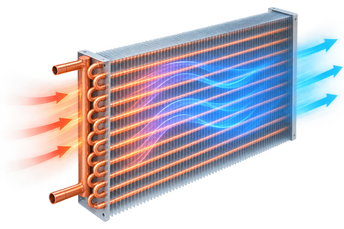
Build a fin-tube coil from its face size, row count, tube and fin data, and get the tube count, total tube length, built mass, water volume and heat-transfer area — with a dimensioned drawing and a 3D model. Geometry only for now: works the same whether the coil ends up running hot water, a glycol mix, or as a wetted evaporative coil.
How to use this calculator
- Enter the coil face size — width along the tubes, height across them — and the number of rows in the airflow direction.
- Set the circuit count — how many parallel water paths the tube passes are split into.
- Enter the tube data — OD (pick a standard size or enter your own), wall thickness, material, and the transverse/longitudinal pitch and layout.
- Enter the fin data — spacing, thickness and material.
- Optionally set the operating parameters — heating or cooling, the fluid (water, ethylene or propylene glycol with its concentration, or DX/evaporative with a refrigerant and saturated evaporating temperature), the fluid's inlet/outlet temperature, the air flow rate, entering temperature and relative humidity, and either the fluid flow rate, the required duty, or the required air leaving temperature — whichever you know. This turns on a sensible-only thermal estimate: duty, leaving air temperature and humidity, and the air-side and fluid-side pressure drop.
- Optionally add a cost estimate — tick "Include a cost estimate" and enter your own unit prices (tube per metre, aluminium sheet per m², fittings per piece, labour, machine/amortisation, other costs, margin %) in whichever currency you work in.
- Read the result: tube count, total tube length, built mass, water volume and heat-transfer area, with a dimensioned drawing and a rotatable 3D model below it — plus the duty, pressure-drop and cost tiles at the top once you've filled in steps 5-6.
What this calculates
The geometry and material results follow directly from what you enter — how many tubes fit in a row, how many rows, how many fins fit across the face width, and the areas and masses that follow from those counts. That part works identically whether the coil ends up circulating hot water, a glycol/water mix, chilled water, or running wetted as an evaporative coil, since the geometry doesn't care which.
If you fill in the operating parameters, the thermal estimate adds a sensible-only energy balance (duty and leaving air conditions from mass flow × specific heat × temperature change — no latent/condensation load, no UA or NTU-effectiveness calculation) plus a pressure-drop estimate: fluid-side from Darcy-Weisbach friction through the coil's own tube length, and air-side from a published Colburn j/f correlation for wet (dehumidifying) plain fin-and-tube coils (Wang, Hsieh & Lin, J. Heat Transfer 119, 1997) evaluated at your geometry's Reynolds number and area ratio. Both are still a first-pass estimate, not a certified coil selection.
Tubes per row = floor((Face height − Tube OD) / Transverse pitch) + 1
Total tubes   = Tubes per row × Rows
Fins          = floor(Face width / Fin spacing) + 1
Tube length   = Total tubes × Face width + Return bends × π × (Transverse pitch / 2)
Return bends: a serpentine circuit needs one U-bend joining every pair of consecutive tube passes, so with N circuits splitting T total tube passes between them, there are T − N joins, each a 180° bend. The bend radius used is half the transverse pitch — the tightest bend that still clears the neighbouring tube's centreline.
Fin area is each fin's full face-width × face-height rectangle, less the round holes every tube pass punches through it, counted on both faces and multiplied by the fin count — plus a small allowance for the bare tube surface exposed in the gap between fins. This is flat-plate area only: it does not add the extra surface a wavy or louvred fin profile provides over a flat one, since that's a manufacturer-specific fin design choice, not a geometry input this tool collects.